

CCTV COVERAGE DESIGN · 26 OCTOBER 2026
CCTV pixel density and camera coverage: an acceptance worksheet
Camera quantity and megapixels do not prove that a person, vehicle or event will be usable in recorded video. Useful coverage starts with an operational purpose at a defined location, then links scene width, pixel density, lens position, lighting, movement and compression to a witnessed image. This worksheet gives builders and facilities teams a practical way to record that evidence.
Visual reference photographs
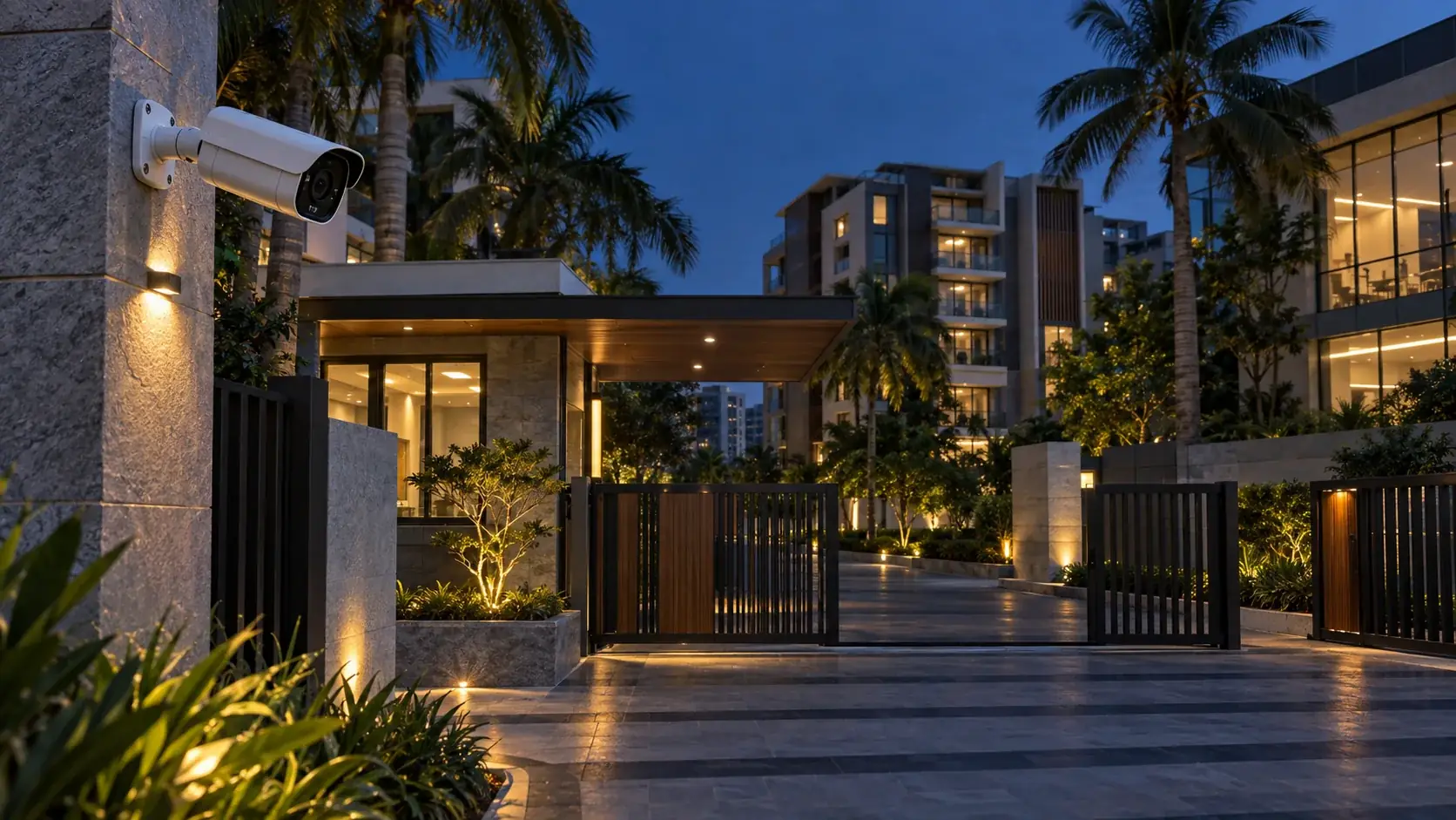
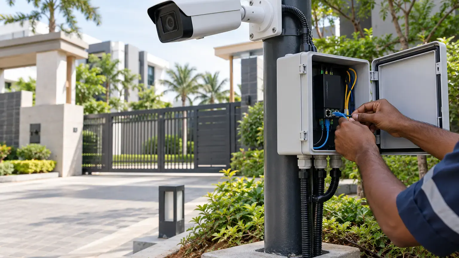
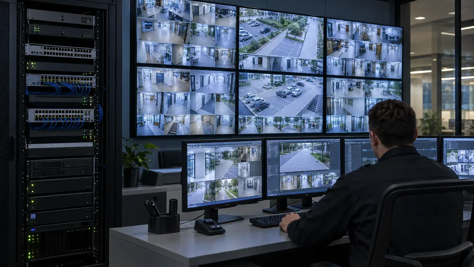
Start with the scene purpose, not a megapixel number
For each camera, mark the exact zone and the required operational task. The 2025 standard uses overview, outline, discern, perceive, characterize, validate and scrutinize. Also state whether the task concerns a face, clothing, vehicle class, number plate, direction of travel, queue, asset or incident sequence. One wide camera can show a large area but distribute its pixels so thinly that important evidence is unusable.
IEC 62676-4:2025 updates application guidance for video surveillance and changes how image-detail requirements are expressed compared with the 2014 edition. Axis notes that the 2025 update adds revised digital-display guidance, frame-rate considerations, illumination information and angle requirements. Therefore, specifications must name the standard edition and chosen task model. Do not mix a legacy DORI table with a 2025 design claim without documenting the conversion.
Purpose row: camera ID · target zone · object or event · required task · maximum target distance · day condition · night condition · operator action · standard edition.
Calculate horizontal pixel density at the target plane
A useful first-pass calculation is horizontal pixel density. Measure the real scene width covered at the target distance, then divide the usable horizontal image pixels by that width.
Horizontal pixel density (px/m) = usable horizontal pixels ÷ scene width at the target plane (m)
Example: a 3840-pixel image covering 15 m gives a theoretical 256 px/m. If the useful region is cropped to 3200 horizontal pixels, the working value becomes about 213 px/m. Record the actual stream resolution and crop, not only the sensor's advertised maximum.
Legacy DORI references commonly use 25 px/m for detection, 63 px/m for observation, 125 px/m for recognition and 250 px/m for identification. Current Axis and Hanwha product material still reports these values for DORI distance. These figures are planning references, not guarantees. Axis explicitly warns that motion, compression, lighting, focus and lens distortion can change the real result, so design margin and field validation remain necessary.
Draw the target plane and the coverage boundary
Pixel density changes with distance and position. A value calculated at the image centre does not automatically apply at a corner, on a sloped driveway or across a wide entrance. Mark the near edge, far edge and side limits of every target zone on the drawing. Record camera height, tilt, lens setting, horizontal field of view, mounting offset and any expected obstruction.
For a gate or lobby, place the target plane where faces are expected, not at the wall behind them. For a vehicle route, calculate at each lane and the actual plate path. For a boundary, divide the route into segments if distance varies materially. Hanwha's DesignPro guidance allows fields of view to be laid out along perimeters, but the final installation must still be checked on site.
Control angle, height and target presentation
A high pixel density cannot correct a poor viewing angle. Measure whether faces are excessively top-down, plates are too oblique or objects are hidden by pillars, trees, parked vehicles, gates or future signage. Record the intended target direction and test more than one approach route where people or vehicles can enter.
Wide-angle lenses increase scene coverage but can reduce pixel density and introduce distortion near the edges. Digital zoom enlarges existing pixels and does not recover missing detail. A motorized varifocal lens helps commissioning, but its final focal length and focus position should be locked or documented after acceptance.
Validate the complete image chain
Test the same stream that will be recorded and exported. Confirm resolution, frame rate, codec, bitrate control, GOP or key-frame interval where applicable, exposure, shutter limits, WDR, noise reduction, focus, IR behavior and corridor rotation. A design-tool image or live main stream does not prove the quality of a lower-bitrate recording profile.
Use representative people, clothing and vehicles only with appropriate permission and site controls. Place a calibrated measurement board or known-size target in each test zone. Capture stationary and moving trials in normal daylight, strong backlight, dusk and the agreed night condition. Save native snapshots or short exports rather than relying on phone photographs of a monitor.
Field result row: camera ID · target zone · measured width · usable horizontal pixels · calculated px/m · lens setting · light condition · target speed · recorded profile · evidence filename · pass, exception or retest.
Separate pixel density from image usability
Passing the arithmetic is only one gate. Inspect motion blur, focus, noise, blocking, glare, IR reflection, shadow detail, headlight bloom, rain response and edge distortion. The selected task should be possible at the farthest and most difficult point in the declared zone, not only directly beneath the camera.
Do not promise face identification, plate reading or analytics performance from pixel density alone. Those outcomes depend on scene geometry, exposure time, optics, processing and the target. If automatic recognition or analytics is required, run a separate application-specific test with the approved software, thresholds and representative conditions.
Coverage acceptance worksheet
- Every camera has a stated operational purpose and target object or event.
- The required task and applicable standard edition are recorded.
- Near, far and side boundaries of each target zone are shown on the plan.
- Camera height, tilt, lens setting and mounting offset are documented.
- Scene width is measured at the actual target plane.
- Usable recorded resolution and crop are used in the pixel-density calculation.
- Centre and edge performance are checked where both are operationally important.
- Faces, plates or other targets are tested along credible approach routes.
- Daylight, backlight, dusk and agreed night conditions are witnessed.
- Stationary and moving targets are reviewed in native recorded exports.
- Focus, blur, noise, compression, glare, IR reflection and obstructions are recorded.
- Camera names and evidence filenames map back to the drawing and schedule.
- Exceptions have a corrective action, owner, due date and retest result.
- Final lens, imaging and recording settings are backed up after acceptance.
Minimum handover pack
Provide the camera schedule, purpose matrix, marked coverage drawing, standard edition, pixel-density calculations, lens and mounting record, recording-profile settings, day and night evidence, native export samples, exception register, final configuration backup and acceptance signatures. Link this record to the night-image usability worksheet, video analytics worksheet and recording retention worksheet.
Primary technical references
- IEC: IEC 62676-4:2025 standard listing
- Axis: Pixel density based on IEC 62676-4:2025
- Axis Lens Calculator
- Hanwha Vision DesignPro: How to use DORI
- Hanwha Vision DesignPro: Set up field of view
Planning CCTV coverage for a property or commercial site?
Share the floor plans, gates, roads, target zones, lighting conditions and recording requirement. We can coordinate camera positioning, network and fiber transport, recording profiles and practical acceptance records around the required operational result.
Discuss CCTV coverage planning ↗