

OPTICAL SPLITTER ACCEPTANCE · 28 OCTOBER 2026
PLC splitter loss and uniformity: a field acceptance worksheet
A splitter label can state 1:8, 1:16 or 1:32 while one damaged output, contaminated connector or wrong port map leaves selected subscribers with less optical margin. This worksheet turns the splitter into a measured component: every output is identified, tested, compared and reconciled with the complete PON loss budget.
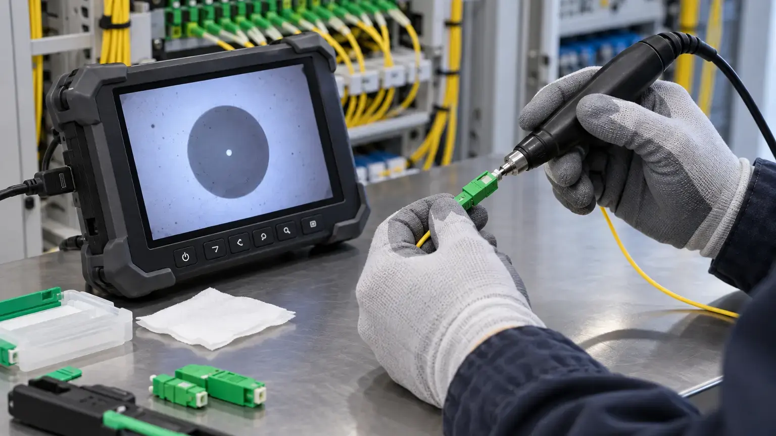
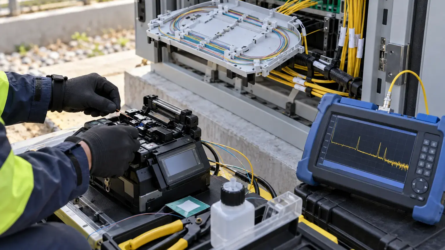
Visual reference photographs

Acceptance is different from selecting the split ratio
The split ratio determines how optical power is divided, but it does not prove that an installed component meets its datasheet or that all subscriber ports are comparable. ITU-T G.671 covers transmission characteristics for optical branching components, including insertion loss, uniformity, reflectance, polarization-dependent loss and directivity. Field acceptance normally focuses on measurable insertion loss, port spread, identification and integration with the link budget.
Use the exact manufacturer's specification for the supplied model. A current Corning 1x32 PLC splitter listing, for example, specifies maximum insertion loss, uniformity, polarization-dependent loss, directivity and an operating wavelength range. Those values are product-specific, not universal limits for every 1x32 device.
Splitter identity row: site · enclosure · manufacturer · part number · serial or batch · configuration · connector type and polish · operating wavelength range · input ID · output range · specification revision.
Understand ideal loss, excess loss and measured loss
An equal splitter has unavoidable theoretical division loss:
Ideal split loss (dB) = 10 × log10(N)
Approximate excess above ideal (dB) = measured insertion loss − ideal split loss
For N equal outputs, ideal loss is about 3.01 dB for 1:2, 6.02 dB for 1:4, 9.03 dB for 1:8, 12.04 dB for 1:16 and 15.05 dB for 1:32. Real measurements also include component excess loss, connector loss, reference-cord effects and measurement uncertainty. FOA describes the same distinction and notes that testing reveals both excess loss and variability between outputs.
Do not fail a splitter merely because measured loss exceeds the ideal value. Compare each result with the exact component maximum and the project method. Conversely, a branch can fit the total PON budget while the component still has an abnormal port that should be isolated before handover.
Calculate uniformity across all outputs
Uniformity is the spread between the highest-loss and lowest-loss outputs under the same test setup:
Splitter uniformity (dB) = maximum measured output loss − minimum measured output loss
Example: if a 1x8 splitter measures from 10.1 dB to 10.8 dB at one wavelength, uniformity is 0.7 dB. If the product maximum is 1.0 dB, the spread passes that criterion, subject to every individual port also meeting its insertion-loss limit. The numbers are illustrative.
Keep the port sequence visible. A spreadsheet that stores only minimum, maximum and average values can hide the fact that the same physical output is worst at several wavelengths or after retermination.
Prepare a repeatable OLTS test
- Confirm the splitter is disconnected from active network signals.
- Use a stabilized source and calibrated optical power meter or a suitable OLTS.
- Select wavelengths required by the project, product and PON plan.
- Inspect, clean and reinspect all reference-cord and splitter connector end faces.
- Use reference cords with the correct connector type and polish. Never mate APC to UPC.
- Set the reference using the documented method and do not change the source connection afterward.
- Secure the launch cord so bending or movement does not change the reference.
- Record meter units, wavelength, reference value, adapter arrangement, date and operator.
FOA recommends a double-ended method before installation and testing at working wavelengths. EXFO notes that the selected OLTS must have enough dynamic range for the splitter and full PON loss. Generic certification profiles may not include splitter thresholds, so enter fixed project limits rather than accepting an unrelated automatic pass or fail result.
Test every port and required direction
For downstream component testing, connect the source to the common input and move the meter reference cord through every output. Record each output by permanent port ID. For upstream testing, reverse the direction according to the approved method. FOA states that splitters are bidirectional elements and should be tested in both directions, with every output and both inputs tested for a 2:N device.
Do not infer 32 results from a sample of three ports. One contaminated adapter or damaged pigtail is precisely the type of localized defect the acceptance test should catch. If a result is high, inspect and clean, reconnect once, repeat the same port, then use a known-good cord or adapter as a controlled substitution. Document both the original and repeat result.
Measurement row: splitter ID · direction · wavelength · input · output · reference value · measured power · insertion loss · limit · pass or exception · repeat reason · file or photo.
Use the right wavelengths
A GPON path may use different upstream and downstream wavelengths, and newer PON overlays can add other bands. Select test wavelengths from the splitter operating range, network technology and project acceptance plan. FOA gives 1310 nm upstream and 1490 or 1550 nm downstream as common GPON examples, while EXFO recommends dual- or triple-wavelength capability for PON applications.
Do not substitute 1550 nm for 1490 nm without documenting why the method permits it. Also avoid connecting an ordinary source or meter arrangement to a live PON without an approved filtered test method and incoming-power check.
Control port mapping before installation
Label the splitter input and each output to match the fiber allocation record, ODF or FDB port, building, floor, unit or service area. Verify continuity before closing the enclosure. A good optical result attached to the wrong apartment record creates a future restoration problem.
For preconnectorized modules, record the adapter position and output identifier. For bare or spliced pigtails, record fiber color, tube, tray, splice position and destination core. Photograph the final routing without exposing sensitive customer information.
Reconcile component results with the installed PON
After installation, measure end-to-end loss from the appropriate endpoints and compare it with the calculated link budget. The installed path includes feeder fiber, connectors, splices, splitter loss, distribution fiber and drop connections. Component acceptance does not replace end-to-end testing.
Predicted branch loss (dB) = feeder fiber loss + connector loss + splice loss + splitter insertion loss for that port + distribution and drop loss
Branch variance (dB) = measured end-to-end loss − predicted branch loss
A branch variance outside the approved tolerance should be investigated against the port's measured splitter loss, connector inspection, splice record, route length and bend condition. Do not average all subscribers together and hide one weak branch.
Use OTDR evidence carefully around splitters
An OTDR is valuable for locating installed events, but a high-ratio splitter creates a large loss and branch ambiguity. A trace from the common input can combine backscatter from many outputs, while testing from each subscriber side gives a different view. FOA explicitly notes that OTDR splitter testing is not the same in each direction.
Use launch and receive arrangements, PON-capable settings and a route map. Keep native traces and document the tested direction. Do not use an automatically labelled splitter icon as a substitute for the port-by-port insertion-loss worksheet.
Field acceptance worksheet
- The exact splitter model, ratio, serial or batch and datasheet revision are recorded.
- Connector type, polish and operating wavelength range match the design.
- The common input and every output have permanent IDs.
- Reference cords and splitter interfaces are inspected and cleaned.
- The source, meter, calibration status and reference method are recorded.
- The test wavelengths match the approved PON plan.
- The OLTS dynamic range exceeds the expected component or link loss.
- Every output is tested, with no sample-only acceptance.
- Required upstream and downstream directions are completed.
- Each insertion-loss result meets the product and project limit.
- Maximum, minimum and uniformity are calculated per wavelength and direction.
- Repeated measurements retain the original result and corrective reason.
- Output IDs map to the correct destination fibers and service areas.
- Installed end-to-end loss is reconciled with the measured splitter port.
- OTDR files identify direction, launch arrangement and splitter location.
- Exceptions, quarantined ports and replacements are traceable.
- The final register, native files, photos and sign-off enter the handover pack.
Minimum handover pack
Provide the splitter datasheet, identity and batch record, input and output map, reference method, instrument details, port-by-port loss table, uniformity calculation, wavelength and direction record, connector inspection status, repeat-test history, installed branch-loss reconciliation, OTDR references and approved exceptions. Link this record to the split-ratio design guide, connector inspection worksheet and FTTH handover testing guide.
Primary technical references
- ITU-T G.671: Transmission characteristics of optical components and subsystems
- FOA: Optical splitter testing
- FOA: Testing fiber optic splitters and passive devices
- EXFO: FTTx PON technology and testing
- EXFO: Insertion-loss testing of passive optical splitters
- Corning: Example 1x32 PLC splitter optical specifications
Accepting splitters for an apartment, campus or ISP PON?
Share the splitter schedule, PON technology, connector type, loss budget and port map. We can coordinate inspection, port-by-port measurement, splicing, installed-link testing and handover records around the approved design.
Discuss splitter acceptance ↗