

OPTICAL FIBER RELIABILITY · 25 OCTOBER 2026
Fiber splice closure sealing and re-entry: a field acceptance worksheet
A low-loss splice is only one part of a reliable joint. The closure must also hold the cable, protect tubes and fibers, keep water and dirt outside, remain identifiable, and allow future crews to re-enter it without disrupting live services. This worksheet gives builders, LCOs, MSOs, ISPs and facility teams a practical acceptance record for buried, chamber, pole and building-entry closures.
Visual reference photographs
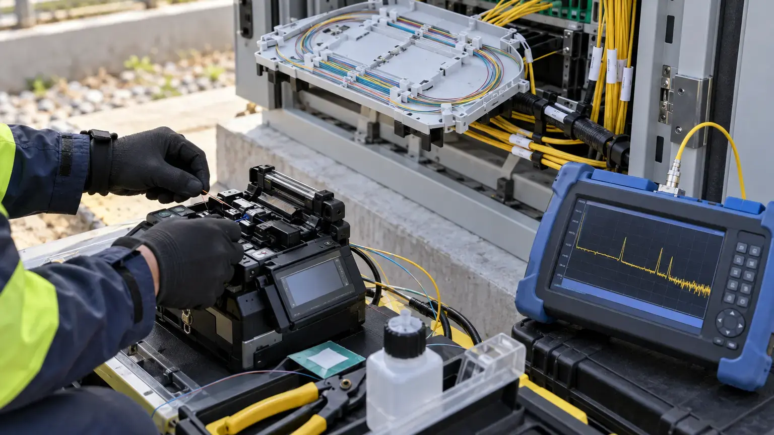


Treat the closure as an engineered assembly
Do not select a closure only by splice count. Record the environment, orientation, cable construction, cable outside diameters, number and type of entries, mid-span access, splice tray family, growth allowance, mounting method, water exposure and re-entry expectation. Confirm that the exact entry kit, seal, strength-member hardware and tray accessories support every cable being installed.
The FOA Installation Standard 2025 requires an environment-appropriate closure, cables secured at entry, suitable fiber and tube lengths, bonding of conductive elements where applicable, proper sealing and testing against moisture ingress, and secure mounting of the closure and service loops. Use this as an acceptance framework, while taking dimensions, torque, consumables and test limits from the selected manufacturer's current instructions.
Selection row: closure ID · route and chamber ID · manufacturer and model · environment · orientation · cable types and diameters · entry-kit references · tray capacity used and spare · conductive elements · approved instruction revision.
Control cable entry before routing fibers
Mark each cable before opening the jacket. Record the measured preparation length and identify elements retained for strength-member clamping, sheath retention, bonding or water blocking. A cable that is optically healthy can still pull or piston inside the closure if its mechanical elements are not anchored as designed.
Use the manufacturer's diameter range and port instructions for the actual cable. Do not build up an undersized cable with improvised material unless the closure system explicitly permits it. Keep sealing surfaces clean, use only specified consumables, close unused ports with the correct plugs, and position seals without twists, folds or contamination.
Corning's 2178 closure procedure is a useful product-specific example. It defines cable diameter limits, sealing-washer selection, strain relief, tape build-up, gasket lubrication, bolt sequence, torque and flash-test pressure. Those values apply only to the listed closure family. Copy limits from the exact procedure, never from another closure or from memory.
Separate three mechanical functions
A robust entry normally has three distinct jobs: seal the cable jacket against the environment, restrain the cable sheath against pullout, and capture the strength member so external movement is not transferred to fibers. If the cable contains armor, messenger wire or another conductive element, document the approved bonding and grounding arrangement separately.
Acceptance should show each function, not just a photograph of a closed dome. Photograph the prepared cable, installed strength-member clamp, sheath restraint, entry seal and any bond connection before trays cover the work. Confirm that the cable approach does not load the seal sideways.
Cable-entry row: cable ID · port ID · measured diameter · permitted range · preparation dimension · strength-member capture · sheath restraint · seal code · unused-port plug · bond reference · photograph IDs.
Route tubes and fibers for operation and re-entry
Buffer tubes should reach the intended tray without sharp bends, crossed hinges or pressure from the cover. Secure tubes at designed retention points and keep controlled length for tray access. Store bare fiber within routing features, maintain the specified bend radius, seat every splice protector fully, and confirm no fiber crosses a screw, latch, gasket or stacking point.
The FOA splice-closure reference warns that tray covers can pinch fibers and that breaks close to a splice can be hard to distinguish from a poor splice. Inspect routing and continuity before stacking trays. Verify each completed splice with the agreed test method before sealing. A fusion splicer's estimated loss is process feedback, not the final acceptance record.
Label trays, tubes and fibers so the next technician can find a circuit without moving unrelated live fibers. Link every splice to the cable and core identifiers in the as-built schedule. Store and identify spare fibers rather than leaving an anonymous bundle.
Seal and test by the exact product procedure
Inspect the complete sealing path immediately before closure. Check gaskets, O-rings, gel blocks, cable seals, plugs, mating flanges and hardware for dirt, cuts, displacement and missing parts. Use only approved lubricant, cleaner, tape, sealant and replacement parts.
Where a flash-test valve exists, apply only the manufacturer's stated medium, pressure, test solution and sequence. The Corning 2178 procedure and CommScope FOSC 450 instructions both describe a 5 psi flash test for those specific products, followed by pressure release. This is not a universal value. Never pressurize an enclosure not designed for it.
Record the model, procedure number, specified limit, applied pressure, inspection duration, leak-detection method, result and pressure-release confirmation. If leakage is found, reopen and correct the assembly using the product procedure. Do not hide an unverified leak path with external sealant.
Plan re-entry before first acceptance
Re-entry is a controlled change. Retrieve the current splice schedule, route drawing, tray plan, photographs and optical baseline. Identify live services, proposed fibers, spare capacity, permitted ports and the exact resealing kit. Record who authorizes the change and how services will be monitored.
Clean the exterior before opening. Release retained pressure using the instructions. Open clamps or bolts in the specified sequence, support the cover and trays, and avoid moving unrelated cables. Photograph the as-found condition and note water, corrosion, insects, displaced seals, cable movement, strained tubes, unlabeled fibers or undocumented splices.
After the change, update the tray and core records, inspect existing fibers, reseal using the current procedure, repeat the required seal test, and take a new optical baseline for affected paths.
Failure clues that should stop acceptance
- Water marks, sediment, corrosion or contamination inside the fiber-management area.
- A cable diameter outside the entry kit's approved range.
- Missing strength-member capture or visible cable pullout.
- Improvised tape, putty, sealant, plugs or mixed parts.
- A dirty, cut, twisted or incorrectly reused gasket, O-ring or gel block.
- Fibers or tubes crossing a sealing face, tray hinge, bolt path or cover edge.
- Records that do not match the physical closure.
- A pressure test without a product-specific procedure, or no pressure-release record.
- A closure resting in water, hanging from cables or unsafe to re-enter.
Field acceptance worksheet
- Closure model and environment rating match the placement.
- Every cable and port is identified.
- Cable diameters fit exact entry-kit limits.
- Preparation dimensions come from current instructions.
- Sheath restraint and strength-member capture are complete.
- Conductive elements are bonded and grounded where required.
- Unused ports have correct plugs.
- Buffer tubes are retained and clear of sealing faces.
- Splices are seated and trays move without strain.
- Tray, tube, cable and core labels agree with records.
- Optical verification is complete before sealing.
- Sealing components passed inspection.
- Clamp or bolt sequence and torque follow the procedure.
- The specified seal test passed and conditions were recorded.
- Temporary test pressure was released where required.
- Closure and service loops are supported and accessible.
- Photographs, exceptions and re-entry history are retained.
Minimum handover record
Retain the closure ID and location, manufacturer and model, instruction revision, cable and port schedule, cable diameters, preparation measurements, entry-kit and consumable codes, tray allocation, splice schedule, bonding record, before-close photographs, optical-test references, seal-test record, exceptions, mounting photographs, acceptance signatures and re-entry history. Link it to the fiber core allocation worksheet and fiber testing acceptance guide.
Planning or maintaining an OFC backbone?
Share the cable schedule, route, closure model, splice count and testing requirement. We can align installation, splicing, closure acceptance and handover records around the actual site scope.
Discuss the fiber scope ↗